How are you all? Hope you are well. Alhamdulillah I am also well. In today's post, I am going to share with you an astable multivibrator circuit diagram.
.png)
This circuit diagram I have made using an NE555 timer IC. This circuit produces a continuous output signal, such as a pulse generator, and it can be used in various applications, such as timing devices, waveform generation, and signal processing, and many more, etc.
| Components used and their functions: |
|---|
NE555 Timer IC:
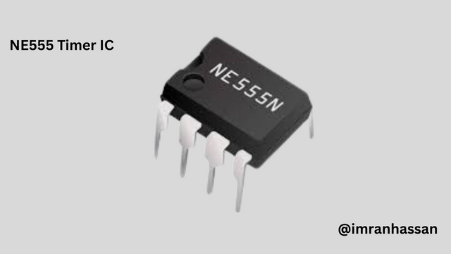
This is the main component of the circuit, which generates timing and pulses.
Resistors (RA and RB):
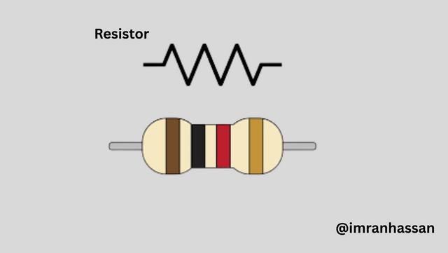
These resistors help in determining the duration and frequency of the two output pulses.
Capacitor C1-C2 (0.01μF):
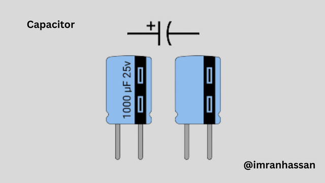
The capacitor sets the timing interval in conjunction with the resistor. This is helpful in ensuring the proper functioning of the circuit.
| Step 1: Connection of NE555 IC |
|---|
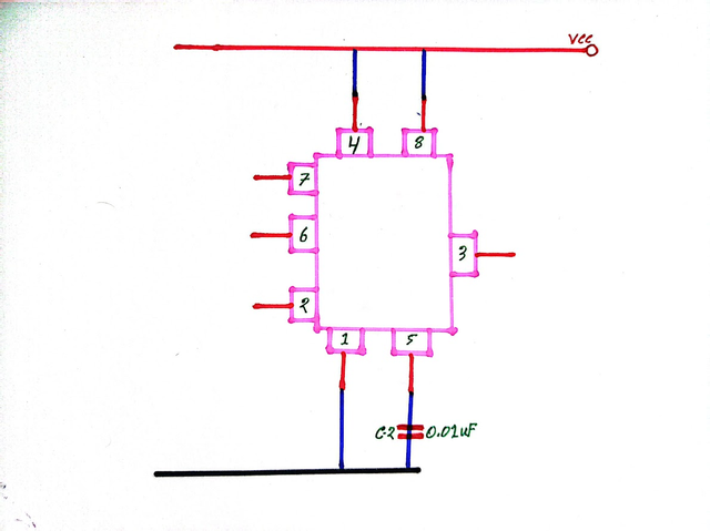
First, I drew the pinouts of the NE555 timer IC. Then, I connected the power supply to pin 8 and pin 1 of the IC, then I connected a 0.01μF capacitor from pin 5, Control Voltage, to ground, which is essential for the proper functioning of the circuit.
| Step 2: Connecting Pins 7, 6 and 2 |
|---|
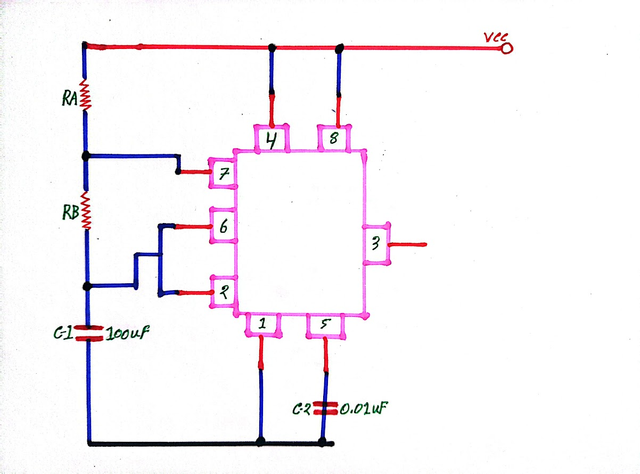
Then I connected a resistor A to pin 7. Next, I connected resistor B and a 100μF capacitor to pin 6 and pin 2, which helps in determining the duration of the output pulse. One thing we will keep in mind is that if we want to increase the duration of this circuit, then we have to increase the value of the resistor and capacitor.
| Step 3: Input and Output Voltage |
|---|
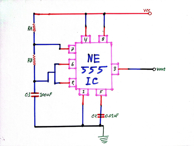
Then finally, pin 3 is used as the output voltage. Proper connection of the input and output signals ensures the functioning of the circuit.
| conclusion |
|---|

An astable multivibrator circuit made using an NE555 timer IC is used for timing and signal generation. An astable multivibrator generates continuous pulses.
| NE555 Timer IC Pin Out and Their Functionality, |
|---|
| Pin Number | Pin Name | Function |
|---|---|---|
| 1 | Ground (GND) | Ground Connection |
| 2 | Trigger (TRIG) | Triggering IC |
| 3 | Output (OUT) | Output Signal |
| 4 | Reset (RST) | Reset Function |
| 5 | Control Voltage (CV) | Output Control |
| 6 | Threshold (THRS) | Timing Setting |
| 7 | Discharge (DIS) | Capacitor Discharge |
| 8 | VCC | Power Supply |